- English
- Español
- Português
- русский
- Français
- 日本語
- Deutsch
- tiếng Việt
- Italiano
- Nederlands
- ภาษาไทย
- Polski
- 한국어
- Svenska
- magyar
- Malay
- বাংলা ভাষার
- Dansk
- Suomi
- हिन्दी
- Pilipino
- Türkçe
- Gaeilge
- العربية
- Indonesia
- Norsk
- تمل
- český
- ελληνικά
- український
- Javanese
- فارسی
- தமிழ்
- తెలుగు
- नेपाली
- Burmese
- български
- ລາວ
- Latine
- Қазақша
- Euskal
- Azərbaycan
- Slovenský jazyk
- Македонски
- Lietuvos
- Eesti Keel
- Română
- Slovenski
- मराठी
- Srpski језик

ENGINEER TALKS Ep.04: Marine Cleat Sizing & Load Limits: Preventing Mooring Failures in 316SS Cleats
At Andy Marine, we believe that practical manufacturing knowledge is one of the most valuable assets built over time.
Inside our workshop, there are engineers, production specialists, and experienced technicians who have spent years working with stainless steel marine hardware — from material selection and casting processes to finishing and quality control.
Many of these insights are learned through daily production experience: understanding why a component fails, how different materials perform in marine environments, and what details truly matter when developing reliable hardware.
However, this practical knowledge is often shared only within the workshop and rarely reaches customers who are making sourcing and engineering decisions.
ENGINEER TALKS is our effort to organize these conversations and share the manufacturing experience behind marine hardware.
Through this series, we discuss materials, production processes, design considerations, and real-world lessons from the perspective of a marine hardware manufacturer.
Today's ENGINEER TALKS Ep.04 is presented by Engineer Wu, written by me the editor.
When a marine cleat fails under load, the component itself is rarely the only cause. In most field cases, cleat failures are system failures—resulting from the interaction between mechanical load paths, deck mounting structures, fastener selection, installation methods, and material quality.
From our experience manufacturing 316 stainless steel marine hardware and structural castings at Andy Marine, understanding cleat failures requires analyzing how forces transfer from the dock line through the fitting, fasteners, and finally into the vessel's deck structure.
By identifying these failure mechanisms, boat builders, sourcing engineers, and maintenance teams can make better decisions during hardware specification, installation, and long-term maintenance.
1. Fastener Pull-Out and Thread Failure
1.1 Field Observation & Mechanism
One of the most common failure modes in marine cleat installations is fastener disengagement, where mounting bolts loosen, pull through the deck structure, or experience thread damage under high loading conditions.
This often occurs during dynamic events such as storm surge, sudden wave impacts, or repeated loading cycles.
Failure Chain Summary
Trigger: Dynamic surge loads from storm conditions or wave impacts introduce sudden tensile stress into the cleat mounting system.
Mechanism: When this tensile force exceeds the load capacity of the fastener system—which depends on bolt material, thread engagement length, installation torque, and deck substrate condition—the connection begins to fail.
Failure Outcome: Thread damage or complete bolt pull-out from the deck structure.
Contributing Factor: Crevice corrosion in poorly sealed reas progressively reduces the effective strength of stainless steel fasteners, especially in continuous saltwater exposure.
Mechanically, when the tensile force applied to the cleat exceeds the load capacity of the fastener system, failure occurs.
The actual strength of the connection depends not only on the bolt material, but also on thread engagement length, installation torque, deck structure, and environmental exposure.
Over time, crevice corrosion in poorly sealed areas can reduce the effective strength of stainless steel fasteners, especially in continuous saltwater environments.
1.2 Preventive Engineering Solutions
Installation Controls
- Ensure sufficient thread engagement length, typically 1.5–2 times the fastener diameter when fastening into metal substrates.
- Apply suitable marine sealant beneath bolt heads and washer surfaces to reduce water intrusion.
- Follow specified torque values during installation. Excessive tightening can introduce unnecessary preload and reduce remaining load capacity.
Component Selection
- Specify A4-70 or A4-80 (316 stainless steel) fasteners for marine load-bearing applications.
- Avoid self-tapping screws as primary fasteners for mooring cleats. Through-bolted connections are preferred whenever structural loads are involved.
2. Deck Interface Failure and Insufficient Backing Support
2.1 Field Observation & Mechanism
A cleat that pulls away from the deck together with a section of fiberglass laminate is usually a sign of mounting structure failure rather than cleat body failure.
When a cleat is installed with only small washers beneath the deck, loads become concentrated over a limited area.
On cored decks, such as balsa or foam sandwich structures, excessive compression can damage the core material. Once the core loses structural integrity, the laminate may flex, allowing water intrusion and progressive delamination.
Without Backing Plate
Higher RiskWithout a backing plate, fasteners transfer load through small washers, creating concentrated point loading on the underside of the deck.
On cored decks, this localized pressure compresses and crushes the core material (balsa or foam).
Once core integrity is lost, the deck laminate begins to flex repeatedly, leading to water ingress, progressive delamination, and eventual structural failure.
With Backing Plate
RecommendedA backing plate (G10 composite or 316 stainless steel) extends beyond the cleat footprint, distributing the load across a much larger deck area.
This significantly reduces local stress concentration on the laminate and prevents core compression damage.
The result is a stable, long-term load path that preserves deck integrity even under repeated high-load conditions.
2.2 Preventive Engineering Solutions
Installation Controls
- For cored decks, consider core reinforcement methods such as removing damaged core material around the mounting area and replacing it with high-density epoxy filler.
- Use backing plates extending beyond the cleat footprint to distribute loads across a wider structural area.
Component Selection
- Use G10 composite backing plates or marine-grade 316 stainless steel backing plates where appropriate.
- Select backing plate thickness based on cleat size, expected load, and deck structure.
- Chamfer backing plate edges to reduce local stress concentration on fiberglass surfaces.
Recommended Reading Looking for baseline hardware dimensions and load ratings for your deck outfitting project? Review our consolidated table in ENGINEER TALKS Ep.16: Boat Cleat Sizing Chart.
3. Off-Axis Load and Excessive Moment Loading
3.1 Field Observation & Mechanism
Marine cleats are generally designed to handle loads transferred close to the deck plane.
A common cause of overload is incorrect line routing, such as dock lines running upward to a high quay wall or pulling sideways without proper fairlead alignment.
High-Angle Load
Higher RiskWhen a dock line pulls upward at an angle, the cleat horn acts as a lever arm above the deck surface.
This converts a portion of the line tension into a bending moment, dramatically increasing tensile stress on the forward mounting bolts and the deck laminate beneath them.
The resulting prying effect can overload fasteners and cause the cleat base to lift on one side—even when the nominal line tension is within the cleat's rated capacity.
Parallel Load
PreferredWhen the dock line runs parallel to the deck surface, the load transfers as shear force distributed evenly across the cleat base and all mounting fasteners.
With minimal lever arm effect, tensile stress on individual bolts remains low, keeping the fastener system well within its safe working range.
This is the optimal load path that marine cleats are engineered to handle, maximizing the hardware's rated capacity and service life.
When a line pulls upward or sideways at an angle, the height of the cleat horn creates a lever arm.
This converts part of the load into a bending moment, increasing tensile stress on the mounting bolts and deck interface.
The actual increase depends on cleat geometry, bolt spacing, and loading direction.
3.2 Preventive Engineering Solutions
Installation & Layout Controls
- Use fairleads, chocks, or hawse fittings to guide incoming lines and reduce extreme pulling angles.
- Align the cleat base with the primary direction of expected loading whenever possible.
Component Selection
- For applications with unavoidable vertical loading, consider low-profile cleats that reduce the distance between the loading point and deck surface.
- For larger vessels or higher loads, four-bolt rectangular base cleats generally provide better resistance against overturning moments compared with smaller two-bolt designs.
4. Internal Casting Defects and Structural Fracture
4.1 Field Observation & Mechanism
Some cleats fail through sudden fracture without obvious deformation or external corrosion.
Inspection of the fracture surface may reveal a rough, porous internal structure, indicating possible casting defects such as gas porosity or shrinkage voids.
Hidden Defect Chain
What You See vs. What You Don't: The cleat exterior presents a smooth, polished surface with no visible flaws. Internally, however, gas porosity or shrinkage voids from inadequate casting process control may be present.
Structural Degradation: These internal defects reduce the effective load-bearing cross-section and introduce stress concentration points within the casting.
Failure Progression: Under repeated loading cycles, fatigue cracks initiate from these internal weak points, propagating through the material until the remaining section can no longer sustain the applied load.
Final Outcome: Sudden, brittle structural fracture with little to no prior visible warning.
In investment casting, factors such as mold design, gating systems, melt quality, and process control influence internal material integrity.
Although polishing can create a flawless external appearance, internal defects may reduce the effective load-bearing area and create stress concentration points.
4.2 Preventive Engineering Solutions
Manufacturing & Quality Controls
- Select suppliers with controlled investment casting processes, including proper gating design, melt quality management, and inspection procedures.
- Apply appropriate non-destructive testing methods, such as dye penetrant inspection for surface defects or radiographic inspection for critical components.
Material Verification
- Ensure components are produced from verified marine-grade 316 stainless steel (CF8M) rather than lower corrosion-resistant alternatives.
- Use chemical composition testing to confirm chromium, nickel, and molybdenum content meets required specifications.
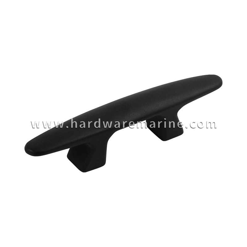
Cleat designed for heavy-duty use. 316 stainless steel with coatings bringing doubled protection against corrosion and scratch.
BROWSE →How to Diagnose Marine Cleat Failures
When investigating a failed cleat, engineers typically analyze the failure pattern before replacing the component.
| Failure Appearance | Possible Cause |
|---|---|
| Bolt pulled out together with fiberglass laminate | Deck structure or backing failure |
| Threads damaged or fastener pulled from fitting | Insufficient fastener strength or engagement |
| Cleat lifts on one side before failure | Excessive moment loading from angled pull |
| Clean fracture through cleat body | Casting defect, fatigue, or overload |
| Corrosion around fastener area | Poor sealing or crevice corrosion |
Failure analysis helps determine whether the solution requires a stronger component, improved installation, or a different load-management approach.
Failure Mode & Solution Matrix
| Failure Mode | Root Mechanical Cause | Primary Indicator | Solution |
|---|---|---|---|
| Fastener Pull-Out | Tensile overload; insufficient engagement; corrosion | Bolts pull out or threads fail | Use 316 fasteners, proper sealing, and through-bolted installation |
| Deck Core Crushing | Concentrated loading on laminate/cored structure | Fiberglass cracking; deck deformation | Reinforce core and install suitable backing plates |
| Moment Loading Failure | Excessive vertical or lateral load angle | Cleat tilting; bolt overload | Improve line routing and select suitable cleat geometry |
| Brittle Body Fracture | Internal casting defects or fatigue damage | Clean fracture surface; internal voids | Control casting quality and verify material integrity |
Failure prevention starts before installation—with proper material selection, structural design, and manufacturing control.
Andy Marine supports yacht builders, marine equipment manufacturers, and distributors with OEM/ODM stainless steel marine hardware development, including investment casting, precision machining, and customized structural components.
From initial engineering drawings to finished production, our goal is to help customers develop reliable marine hardware designed for demanding saltwater environments.